Hands-On,
Data-Driven.
I'm Jaden, a B.S. graduate in Applied Physics (Creighton University) and Mechanical Engineering (WashU) and soon-to-be M.S. Aerospace Engineering graduate from WashU.
Chief Engineer, Testing Coordinator, Lead Driver, and Driver Coach of WashU Racing; former Aerodynamics and Composites Lead.
The WUFR-26: 25th of 131 teams, the highest-performing car in WashU Racing history, and a perfect 100/100 design score.
About
A decade in the shop before university. Where the instinct for engineering comes from.
↗
Education
Physics at Creighton, mechanical and aerospace engineering at WashU.
↗
Racing
Chief Engineer and Aero Lead at WashU Racing; the full technical story of WUFR-25, WUFR-26, and WUFR-27.
↗
Experience
Professional engineering work: from CFD optimization at Bergstrom to a decade at Crocker's Collision Center.
↗
Projects
Independent technical work: a go-kart aero study, an EV charging mechanism, and more.
↗
Contact
Get in touch, or download my résumé.
↗
Education
Three degrees, one through-line:
understand before you build.
My education started with physics, the desire to understand the fundamental rules of nature, and the mathematical language to describe them. I
then layered mechanical and aerospace engineering on top of that foundation. Each degree answered
a question the previous one raised.
B.S. Applied Physics, Minor in Mathematics GPA 3.83/4.0Graduated: May 2026
Physics was the starting point because I wanted to understand why things behave the
way they do, not just how to work with them. Applied physics gave me the mathematical
language for forces, fluid behavior, material mechanics: the overall design process.
The minor in mathematics reinforced the toolset. This degree taught everything that engineering assumed.
My Creighton University senior capstone was an aerodynamic investigation of a go-kart body using CFD and a
wind tunnel I built myself. This is where my physics and engineering instinct first converged
formally. That project lives in the Projects section.
Statistical Mechanics
Advanced Differential Equations
Advanced Linear Algebra
Classical Mechanics
Mathematical Methods
B.S. Mechanical Engineering GPA 3.8/4.0Graduated: May 2026
M.S. Aerospace Engineering GPA 4.0/4.0Expected Graduation: May 2027
The physics foundation came first, then engineering degrees taught me to apply it. Beyond the classroom concepts, my education and experience taught me to design
systems, validate simulations against real-world measurements, and make decisions under constraints.
The M.S. in Aerospace Engineering oriented everything toward aerodynamics, vehicle
performance, and structures. This is where my physics background, my work on the
racing team, and my passion collide most directly.
Computational Fluid Dynamics (CFD)
Aerodynamics
Aircraft Performance
Aircraft Design
Fluid Dynamics
Fatigue and Fracture Analysis
Mechanical Behavior of Composites
Mechanics of Continua
For engineers: how this coursework connects to practice
Physics → Engineering → Application
The CFD work in ANSYS Fluent draws on the same Navier-Stokes formulations from physics. The composite manufacturing and structural analysis work on the aero package draws directly from the Mechanical Behavior of Composites course.
The M.S. aerospace coursework feeds directly into the 5-dimensional aerodynamic map currently in development for WUFR-27, where I am mapping CL, CD, and CoP across front ride height, rear ride height, yaw angle, roll angle, and steer angle.
One of a few students selected for Boeing's elite mentorship program based on academic performance and demonstrated
technical leadership within the WashU Racing Aerodynamics sub-team.
Racing — WashU Racing, FSAE
From team member to
running the whole car.
WashU Racing competes in Formula SAE, an international collegiate engineering competition
where student teams design, build, test, and race a formula-style car from scratch each year.
I joined as a general Aerodynamics & Composites member in September 2024, was promoted to Aerodynamics & Composites Lead in
May 2025, and to Chief Engineer & Driver Coach in May 2026.
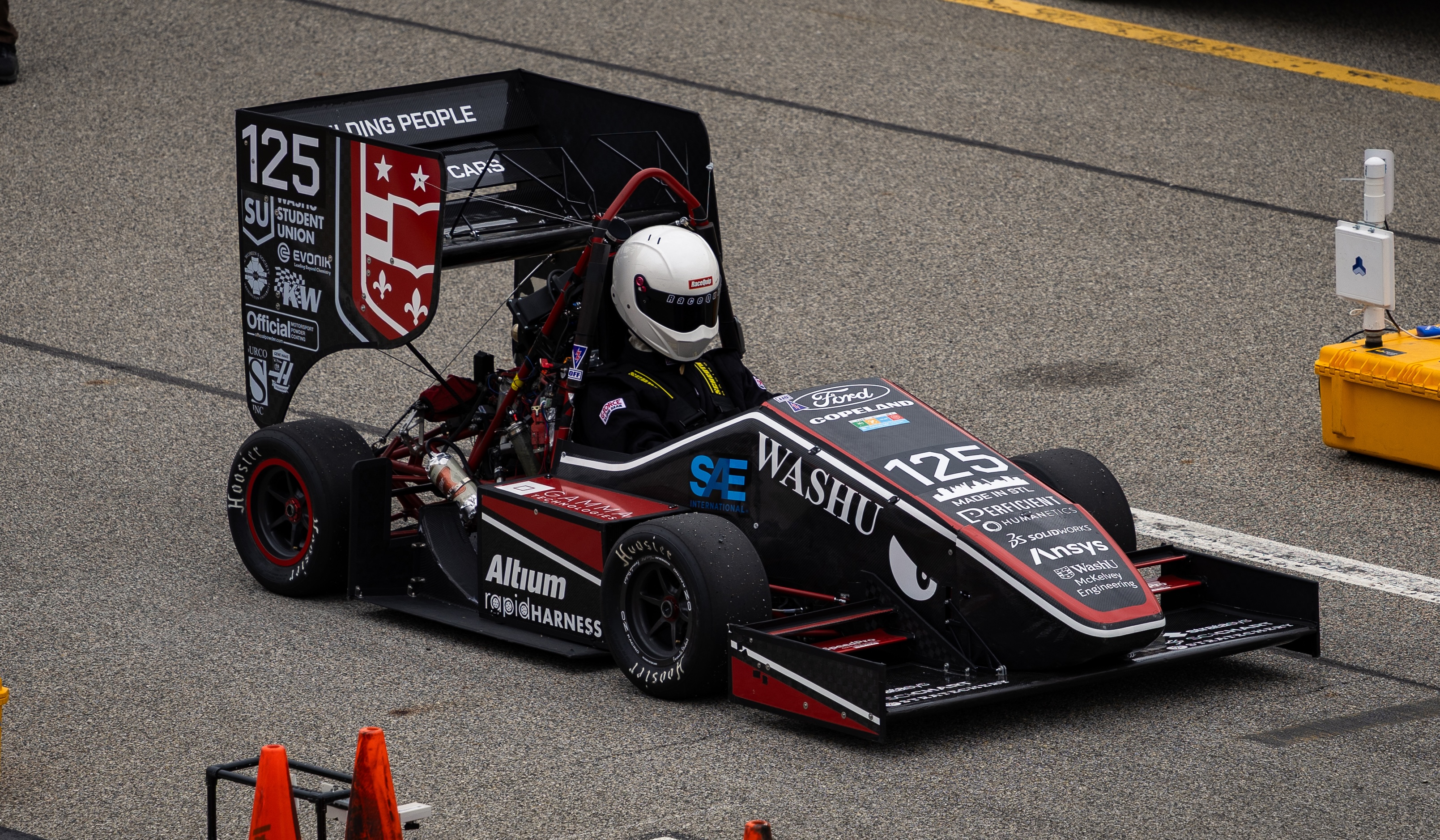
WUFR-26 on track for the acceleration event
As Chief Engineer, my job is to make sure every design and build decision across the six technical sub-teams
(aerodynamics, suspension, chassis, electronics & data acquisition, ergonomics, and
powertrain) serves the same goal: a faster, more consistent car at competition.
I started with the data. Analyzing WUFR-26 competition results identified suspension and
powertrain inconsistencies as the primary drivers of our performance gaps. The vehicle was observed to suffer from lateral favorability, obtaining higher lateral G forces
in left-hand turns. Powertrain experienced a fuel rail pressure loss over time, among other issues, and further testing revealed this pressure loss stemmed from the fuel pump overheating.
From that diagnosis, I set the season's vehicle-level performance targets, informed each system of the major issues affecting their subteams, built the testing plans, and structured
the build program around closing those gaps. Both issues are now being resolved in the WUFR-27 build. I coordinate 60+ engineers and own the
testing schedule and build season from first shakedown through competition weekend.

5‑D aerodynamic map: predicting aerodynamic behavior across five different operating parameters
Race strategy
At competition, I set the race strategy for each dynamic event and communicate it on two levels: to the team's
engineers, so everyone knows the plan and their part in it, and to the driver, so they know exactly how to
approach the event.
Driver coaching
A car is only as fast as its driver can confidently drive it, and a team engineers better when it understands
what the driver feels. I lead the selection of new test drivers, train new competition drivers and build their
confidence, and personally complete the highest-risk data collection drives in our testing program.
I also teach vehicle dynamics to new drivers and to any team member who wants to learn, from both sides: the
engineering that explains what the car is doing, and the driver intuition that tells you it's happening.
Engineers who understand the driver's side design better cars, and drivers who understand the engineering
give better feedback.
For engineers: vehicle-level methodology and testing process
Goal-setting and test structure
Goal-setting starts with competition data: lap times broken down by event segment, dynamic event scores, and on-car data from previous seasons. I used this to identify which systems are underperforming relative to their theoretical potential. In WUFR-26's case, suspension and powertrain inconsistency were the largest offenders.
Testing plans are structured around falsifiable targets: each system has a defined performance envelope to hit before integration, and the full-car testing sequence is designed to isolate variables before competition loads make the data harder to interpret cleanly.
- Six sub-teams: aerodynamics, chassis, electronics & data acquisition, ergonomics, powertrain, suspension
- 60+ engineers across the full program
- Full ownership of test plan creation, scheduling, and execution
- Undertook two key projects to advance the team's predictive and analytical capabilities
- Race strategy for each dynamic event, communicated to both the engineering team and the driver
- Driver development: test driver selection and competition driver training, and, as the team's lead driver, I personally complete the highest-risk data collection drives
Design event: perfect 100/100 team score; aero system 13/15, highest in team history
I led the design, simulation, validation, and manufacturing of the full aerodynamic
package for WUFR-26. The work starts before any geometry is drawn: lap-time simulation
sets the vehicle-level aerodynamic coefficient performance targets, and every downstream design decision is
evaluated against those numbers.
The aerodynamic package was validated against wind-tunnel and on-track data to within
10% across lift coefficient, drag coefficient, and center of pressure, meaning the
simulations used to make design decisions confidently reflect real vehicle behavior.
The aerodynamic package was manufactured in-house by the aerodynamics team, with myself overseeing the mold manufacturing, mold preparation, and
composite layup & curing process. I also oversaw the redesign of the front wing, rear wing, and sidepod mounting system,
reducing mass by 7% below target and improving serviceability and full-team access to critical areas on the car.

Velocity contours of the front wing and axle on the WUFR-26. Simulated in ANSYS Fluent.

Undertray mold preparation for carbon fiber wet layup.
Competition weekend
At competition, I made the trackside calls on aero configuration, gave input on the desired suspension setup between runs, and went
through the rulebook with the technical inspection judges to confirm the car met every rule before it could run.
Defending the design. FSAE design judges are industry engineers, and the event is closer to an
interview than a presentation: they probe every assumption, from why a target was chosen to how you know the
simulation reflects the real car. I walked the judges through the full chain, from lap-time simulation targets
to CFD, correlation against wind-tunnel and track data, and manufacturing, defending each decision with data.
The aerodynamics system scored 13/15, the highest in team history, and WUFR-26 earned a perfect 100/100 design
score. Only teams scoring 100 are considered for design finals; we missed the finals by one or two places and
finished 25th of 131 teams overall after completing every dynamic event.
For engineers: CFD methodology and validation approach
From lap simulation to validated CFD
Aero targets are set using OptimumG lap-time simulation, translating aerodynamic parameter changes into lap time delta. This gives every design decision a quantifiable vehicle-level justification. WUFR-26 targets: CL = -3.2, CD = 1.3, CoP = 40–45% front.
Full-car external aerodynamics are simulated in ANSYS Fluent:
- Reynolds-Averaged Navier-Stokes (RANS) solver
- Pressure-based, incompressible flow conditions
- Spalart-Allmaras turbulence model
- 120 million cell and 50 million cell targets for full and half car simulations, respectively, as per team computational power limitations
Validation is performed against wind-tunnel measurements and on-track instrumented testing, with a target of sub-10% delta across CL, CD, and CoP in straight-line and 20° yaw conditions.
- Mounting system redesign: ~7% mass reduction below target, reduced service time
- Cockpit surface redesign: -CL +2%, CD −4% per CFD
- Pitch, yaw, and roll operating envelope now being fully characterized through the in-progress 5-dimensional aerodynamic map
- Documentation produced for design justification and cross-generation knowledge transfer
Joined WashU Racing as a general member of the Aerodynamics sub-team in my first semester
at Washington University in St. Louis. Led the redesign of the front wing truss for the WUFR-25 car and
heavily contributed to the carbon fiber manufacturing process.
Contributed to the early design and simulation work on WUFR-25
before being promoted to lead the sub-team in May 2025.
Current projects
Two active development programs, both targeting completion for the WUFR-27.
In progress
5-Dimensional Aerodynamic Map
The first aero map in WashU Racing history. We're building a complete picture of how
the aerodynamic package behaves across every condition the car will see at competition,
mapping five parameters: front ride height, rear ride height, yaw, roll, and steer. This gives the
team a data-driven baseline for setup decisions rather than relying on intuition, and it further informs the suspension and powertrain systems about
how aerodynamic performance affects their designs across the vehicle's operating envelope.
Full picture of aerodynamic behavior · March 2027
In progress
Live Telemetry Fuel Calculator
A real-time fuel consumption model integrated into the car's live telemetry display.
During endurance events, fuel management is critical. Running out ends the race,
not using enough sacrifices lap times. This tool will give the driver and race engineers a live
fuel readout so strategy is based on data, not guesswork. In final form, this calculator will not only be used
for real-time race strategy, but also to predict the fuel consumption of new vehicle setups and designs before they ever hit the track.
Live data integration · November 2026
Professional Experience
Engineering in industry
and where it all started.
Two professional experiences that bookend my engineering journey: the family collision shop
where I learned how vehicles actually work, and the CFD internship where I brought
everything I'd learned into a professional engineering environment.
CFD Engineer Intern · Rockford, IL
Bergstrom manufactures HVAC and climate control systems for specialty vehicles. The
challenge I was tasked with: every new design required CFD optimization that was iterated
entirely by hand. Each iteration took one to two weeks, driving long lead times and high costs
across every product development cycle.
I pioneered an automated optimization workflow using ANSYS OptiSLang with Discovery and Fluent
that cut each cycle to three to four hours, letting engineers evaluate hundreds of
geometric variants in the time it previously took to run one. I applied it to two
real products, both of which proceeded with my new, optimized designs: an HVAC unit for a luxury automotive OEM and an air distribution duct for
an agricultural equipment manufacturer. I then wrote a full user manual so the workflow would outlast my internship, advancing the capabilities of every design engineer within the company.
Presenting my automated CFD optimization workflow to company leadership (Aug 2026).
For engineers: the optimization pipeline and measured results
Workflow and results
The pipeline uses ANSYS Discovery for parametric geometry generation and rapid CFD solutions, feeding into OptiSLang for design-of-experiments and response surface optimization.
The key was structuring the parametric model so geometric variations could be explored without manual input at each step.
- Lead time: 1–2 weeks → 3–4 hours
- Luxury automotive OEM HVAC unit: evaporator face-velocity uniformity: 65% → 91%
- Agricultural equipment manufacturer air distribution duct: maximum flow imbalance: 52% → 6%
- User manual written for adoption by company design engineers
Autobody Technician · Watertown, SD · Full-time / seasonal
My family's collision repair shop, and the place I spent most of my childhood.
From 2013 to 2021 I worked there after school and full-time every summer.
From 2021 to 2023, through my first two years of university, I came back
every summer.
The technical range was wide: structural failure diagnosis and repair of collision-damaged
vehicles, chassis repair, MIG welding, metal component fabrication,
body panel repair, and full refinishing & paint correction. What I took from it was less about
any single skill and more about how to read a vehicle as a single unit, made up of hundreds of harmoniously meshed systems.
Crocker's Collision Center, Watertown, SD
Projects
Curiosity with an outcome:
Academic and Personal Projects
Independent and academic projects that sit outside the racing team and professional
experience but share the same approach: define a problem clearly, build or simulate
something to test it, and close the loop with real data.
Creighton University · 2023 – 2024 · Autodesk Fusion 360, Autodesk CFD, physical wind tunnel
Before I had formal CFD training, I wanted to understand how body shape drives
aerodynamic behavior on a vehicle. For my senior capstone, I 3D-scanned a go-kart,
imported the geometry into Autodesk Fusion 360, and made iterative modifications to the body shape to investigate their aerodynamic effects, particularly focusing on drag.
Each variant was simulated in Autodesk CFD to predict the aerodynamic forces it would generate and studied to link the general connection between a vehicle's geometric shape and its aerodynamic performance.
To validate the simulations, I built a makeshift wind tunnel from scratch, because
if I was going to claim the CFD was accurate, I needed physical data to compare it to.
While the wind tunnel was a low-fidelity setup, it was sufficient to measure the drag produced by each body shape variant and compare it to the CFD predictions.
I was unable to observe flow behavior due to the materials and resources available, but the drag measurements were able to at least confirm the forces predicted by CFD to within about 20%.
This led to me more confidently drawing conclusions about the aerodynamic effects of each general body shape modification and the underlying physics driving those effects.
The project wasn't assigned with this scope; the wind tunnel was my own addition.
It was the first time I formally connected physics intuition, computational simulation,
and physical measurement, and it's what pointed me toward aerodynamics as a discipline
worth pursuing seriously.
For engineers: methodology
Methodology
3D scan of physical go-kart → geometry cleanup and parametric modification in Fusion 360 → steady-state CFD in Autodesk CFD across a range of body shape variants → physical wind tunnel testing of representative configurations for validation.
Washington University in St. Louis · Aug – Dec 2025 · SOLIDWORKS, MATLAB
A mechanical design project that was commissioned by a local startup in St. Louis. They desired a completely automatic arm that would
deliver a charging connector from a stationary base to a charging port located in the hood of a vehicle.
Not only would this arm need to solve the deployment challenge, but it also needed to extend up to 5 ft, retract back into a 6 inch package, deliver 5 pounds of axial load, and withstand the loads and environmental conditions present
in an EV charging system. Our solution consisted of a scissor-arm extension mechanism driven by a single lead screw, combined with a passive alignment system on the end effector and 3D-printed components to reduce weight and costs.
The final design was a compact, lightweight, and robust arm that satisfied all requirements and desires.
The mechanism is driven by a single lead screw driven by a stepper motor,
with a five-stage scissor-arm geometry achieving a 10:1 extension-to-retraction ratio.
Arm geometry was optimized using custom kinematic models in MATLAB, and motor
and drivetrain specification was selected through static and frictional torque loss analysis.

Finalized scissor arm and motor CAD assembly

Final assembled prototype, testing axial load with 5 lb payload
For engineers: kinematic model, motor spec, and design constraints
Design and analysis
Arm length, arm count, and deployment angle were optimized using custom kinematic MATLAB models, balancing the structural limits of 3D-printed arm geometry against the target extension ratio and packaging envelope.
- Extension ratio: 10:1 (5 ft extended / 6 in stowed)
- Motor: NEMA 23 stepper with 1605 ball screw, specified via static and frictional torque loss analysis
- Torque safety factor: 1.0 N·m at 5 lb end-effector payload
- Compliant with IEC 61439-7 (high-voltage outdoor operation)

Response surface comparing the arm length and width with total stowed size as the optimization objective

Simple plot displaying arm length to total extension relationship